Tech Tips
The team at Hyperco has been designing and engineering race-winning suspension springs and components for more than 50 years. Tech Tips is a collection of common questions and answers our Engineering team has put together. If you still have questions on any of these topics or if you want to submit your own question, please contact us. We are more than happy to help!

View Tech Tips for Measuring, Maintaining, & Prolonging the Life of Your Suspension Components
Unpredictable spring performance can result in disqualification after the ride height has been measured.
Poor quality springs can lose free length and then seem to stabilize. The problem that can arise is that the performance of the springs is unpredictable. For such springs, this means that it is impossible to know with any degree of certainty what is the free length / installed height at a specific moment of time. This could result in disqualification when the ride height is inspected by technical officials.
The good news is that it is possible to avoid the worry of this problem. Hypercoils are designed and manufactured to maintain their free length and installed height for life. See Hyperco warranty for complete details.
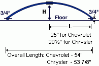
To measure the arch, place the spring on a flat surface with the arch up. Measure from the floor to the bottom of the spring (‘H’ in the diagram), and then subtract 3/4″ from the total length. For the Chrysler, the overall length (eye to eye) is 53 7/8″ and the pin to eye length is 20 1/2″ (‘L’ in the diagram). For the Chevrolet, the overall length (eye to eye) is 54″ and the pin to eye length is 25″ (‘L’ in the diagram).
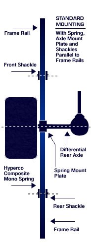
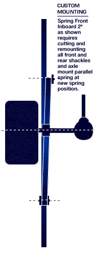
Note: The top of the images is the front as viewed from the bottom of the car.
Remove shackles and axle center mount mounting brackets. Remount brackets to desired new spring position while keeping them aligned and parallel in relationship with the spring. This will eliminate binding and maintain true alignment between spring, bolts, and mounting brackets.
Install Mono Spring. Check alignment. The inner sleeves should not bind inside the spring bushings on both front and rear mounting points.
Bolt spring to axle center mounting plate with poly mounting pad extending 1/4” beyond the edge of the steel mounting plate.
U-bolts should be tightened to 65 ft. lbs. or to the yield of the center mount plate. U-bolts should never come in contact with the spring. It is recommended a heavy gauge rubber or plastic hose be fitted over the U-bolts to ensure there is no metal to composite contact. Take care not to twist spring during this final step. CAUTION: Torque values may vary depending on the hardware used. (Hyperco recommends the use of a lateral control/limiting device or similar device to control/limit the amount of lateral axle movement.)
TIP: After removing shackles and axle mount plate, assemble them to the Composite Mono spring to keep a precise assembly alignment relationship. Then tack weld the assembly to your new mounting position (Always shield springs from welding or exhaust pipes high temperature. This procedure will assure a successful custom-fitted installation.).
NOTE: Disassemble spring and complete welding.
Other Tips for Composite Leaf Springs:
- U-bolts should never come in contact with the composite portion of the leaf spring. Hyperco recommends a heavy gauge rubber or plastic hose be fitted over the U-bolts to ensure that there is no metal to composite contact.
- U-bolts should be tightened evenly to a torque value of 80 to 100 ft. lbs., or until the center mounting plate yields / deflects. The torque value should be checked on a regular basis to ensure adequate and consistent clamping force.
- The mounting pad must extend a minimum of ¼” past the steel mounting plate.
- Additional protection for the composite leaf can be obtained by wrapping all exposed surfaces with high quality duct tape.
- When installing springs it is important to check the alignment. The inner sleeves must not bind inside the spring bushings on both the front and rear mounting brackets.
Whether or not it is necessary to unload the coils in the pit, or block the car while it is being transported depends upon the type of suspension coils you use. If you purchase high-quality springs with the correct length and are also designed for the rigors of professional racing conditions you should not need to jack up the car. You must also ensure that the spring is not being slammed or hammered coil bound. This could happen if the car becomes airborne, and bounces one corner, or hits a curb.
High-performance springs, such as those which we manufacture, will save you time and will not take set. In addition, they will provide you with a performance advantage during the race itself.
‘Rate Overlap’ occurs when the manufacturer’s manufacturing tolerance(s) is more than one-half the rate change desired. For example, assume you are considering a rate change from 475 to 500 lbs., which is a change of 5.3%. Further assume that the spring manufacturer’s tolerance is plus or minus 3%, a tolerance level, which is very common among manufacturers today. It is possible, therefore, that the rate for your 475 lb. Spring could range from 460 lbs. (475 X 97%) on the low end to 489 lbs. (475 X 103%) on the high end. The rate for your 500 lbs. spring could range from 485 lbs. (500 X 97%) to 515 lbs. (500 X 103%). In the worst case, you could be going from a 460 lb. Spring rate to a 515 lb. Spring rate, a 12% variation (remember you were looking for a 5.3% chance!) that would dramatically affect your car’s handling, and leave you scratching your head, wondering what to do next!
At Hyperco, we have invested in material and manufacturing technologies to ensure that our spring rates are accurate and consistent. While we guarantee plus or minus 2 percent tolerances, in actual experience, Hypercoils generally run within 1 percent tolerances, and we do not offer rates that overlap. Consistent rates and manufacturing tolerances allow our customers to develop “setups” that repeat race to race, year to year, and coil to coil. This is one of the reasons many of the top teams in all forms of motor racing use Hypercoils.
The design load is solid load for all rates from 800#/in through 3500#/in. For rates 4000#/in to 5000#/in, the design load is the maximum load that can be applied before the spring takes a set.
You can find the total deflection available by taking the design load and dividing it by the rate. For instance on the 800#/in spring, the design load of 887# divided by the 800#/in spring rate yields 1.09” of deflection. 887/800=1.09.
All of the springs through the 3500#/in rate are understressed and can be compressed to solid thousands of times without affecting free length, rate or load. For any given rate, the springs do not need to be deflected to solid or design load. You can travel them any length you need within that constraint.
To start out, you need to know the approximate load that your vehicle puts on a spring at its maximum through the corner. Then take the initial rate spring you want to use and take it to the maximum deflection point that you see and determine the spring load at that deflection. Subtract that from the total load you are going to need through the corner and that will be the minimum design load from a bump spring that you will need.
For instance: let’s say that you see a maximum of 2340# of load on the right front through a corner and you want to use a 12B0275UHT as your main spring on the right front. Let’s also assume that you have 650# of sprung weight on the right front and that you want to travel the main spring 3.0” additional before the spring rate starts to rise. 650# of sprung load compresses a 275lb/in spring 2.364”. The additional 3” of travel requires another 825lb (3.0” x 275#/in) of load on the spring. 650# + 825# =1475# of force contributed by your main spring. This is now the point where you want the rate to increase. A bump spring is not a stacked spring. It is a nested spring and acts like the inner spring in a dual valve spring set. Therefore the bump spring rate adds to the main spring rate from this point on. Now let’s say you will travel the suspension another 0.750”. 0.750” x 275lb/in spring rate =206# of load from the main spring. Add that to the 1475# and you have 1681#. Subtract the 1681# of load from the required 2340# maximum load that you see and you get 659# of load required in an additional 0.75” of travel. Divide 659lb by 0.75” and you get 878lb/in minimum spring rate needed to achieve this load.
You usually want to round up to the next highest rate and that would be 1000#/in. Divide the 659# load by 1000#/in of bump spring rate and you will find the bump spring deflects 0.659.” That is not too far from the 0.750” of travel we are talking about. Additionally the bump springs can be shimmed to change the “pick-up point” where they come into action. Also, if you want a slightly higher rate feel, there is nothing wrong with trying a 1200#/in rate.
The key point to remember is that using a bump spring creates a “nested spring” configuration where the rates are additive. With stacked springs, the combined rate is always less than the lowest rate spring. With nested springs the combined rate is always greater than each of the single spring rates. The combined rate in our example above would be 1275#/in.; 275#/in from the main spring and 1000#/in from the bump spring.
Hyperco does not know of any portable checker that can measure rate with repeatable results. Portable checkers are adequate for general testing, and for comparing springs of 1000 lb. rate or less. When using portable checking equipment, follow these tips and it will help you get more reliable results.
- Use calibration springs and keep them for reference.
- Use a strong, sturdy frame for your equipment – one that will not bow or flex.
- Make sure the top and bottom plates are parallel.
- Inspect the checking equipment for leaks.
- Use a consistent set of operating procedures: (1) Orient the springs the same way each time and (2) Compress the springs to the pre load, do not “bleed” to it.
Basically, the system works on the principle that two springs working in series share the overall applied deflection. That is a fancy way of saying that when you stack two springs, the combined spring rate drops. With our system, we can lock out one of the two springs during the shock’s deflection. Once this happens, any additional deflection is only moving one spring, so the effective spring rate increases to the active spring’s rate.
Typical Stacked Spring on a Coilover Setup
By picking and choosing the two springs in the assembly, we can give you a fairly broad range of spring rates and rate combinations. The advantage of the adjustable locking ring is that it lets you select where in the shock’s displacement you want the transition to take place. This gives you far more flexibility than dedicated progressive springs. The downside is that the spring stacks can get fairly long. But if you have room for the package, this gives you the chance to have a variable rate setup that you can tune using off-the-shelf springs. In other words, you get more flexibility at a lower cost.
Formulas for Springs in Series - Dual Spring Rate Calculator
For more information on stacked spring configurations and how to achieve dual spring rates, visit our web page or download the Dual Spring Rate Overview Document.
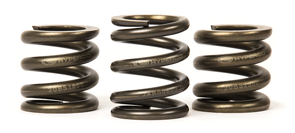
The part number comprises:
FREE LENGTH + ID CODE
For example, Hyperco’s part number: 10 B 0400 would have:
(1) A 10” Free Length
(2) A 2.5” I.D. (see list below for valid codes) and
(3) A rate of 400 lbs. / inch of spring deflection.
FREE LENGTHS:
4, 5, 6, 7, 8, 10, 12, 14, 16 & 18”+
I.D. / O.D. LETTER CODES:
A: 2.25
B: 2.5”
C: 2.0”
D: 1.875”
E: 3.0”
FS: 1.45”
I: 36 mm
M: 60 mm
P: 70 mm
Q: 1.680"
S: 5.0"
SN: 5.0"
SNS: 5.0"
SNU: 5.0"
SNT: 5.0"
SS: 5.0"
Y: 5.0"
SNP: 5.5"
Z: 5.5"
Within the high-performance vehicle industry, there has been discussion about which spring style is recommended for suspension springs applications-- linear rate or progressive rate. To review details on the differences and our expert recommendation, visit our webpage devoted to linear vs progressive rate suspension springs to learn more about the differences between these two spring types and what this could mean for your ride.
Below you will find various formulae that racers have used to evaluate the performance of different configuration options. You may also find our online Spring Rate Calculator helpful.
Solid Height | |
| Solid Height | = (Number of Coils – 0.25) x Wire Diameter |
| For example, for a spring with 14 coils and a wire diameter of 0.5”, the Solid Height would be calculated as follows: | |
| Solid Height | = (14 – 0.25) x 0.5 = 6.875 |
Rate | |
| Rate | = Load (lbs.) ÷ Spring Deflection (in.) |
| For example, if a spring deflects by 2.75” under a load of 300 lbs, the Rate would be calculated as follows: | |
| Rate | = 300 ÷ 2.75 = 109 |
Deflection | |
| Deflection | = Load (lbs) ÷ Rate |
| For example, a spring under a load of 300 lbs with a 109 Rate, the deflection would be calculated as follows: | |
| Deflection | = 300 ÷ 109 = 2.75 |
Load | |
| Load | = Deflection x Rate |
| For example, a spring with a 109 Rate and a 2.75” deflection, the load would be calculated as follows: | |
| Deflection | = 2.75 ÷ 109 = 300 |
Combined Spring RateThis is used when two springs are stacked on top of each other. Combined Spring Rate = Combined Spring Rate = | |
Contact Us
For more information on Hyperco products, capabilities, or resources, contact us.